<strong>OverClockers Work Log HERE
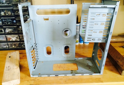
We have decided to add a section dedicated to 3D printing case mods. We will be kicking off this new addition with a build using a doner case. The case is an old one and it’s main structure will be used. So far we’ve stripped down every single piece.
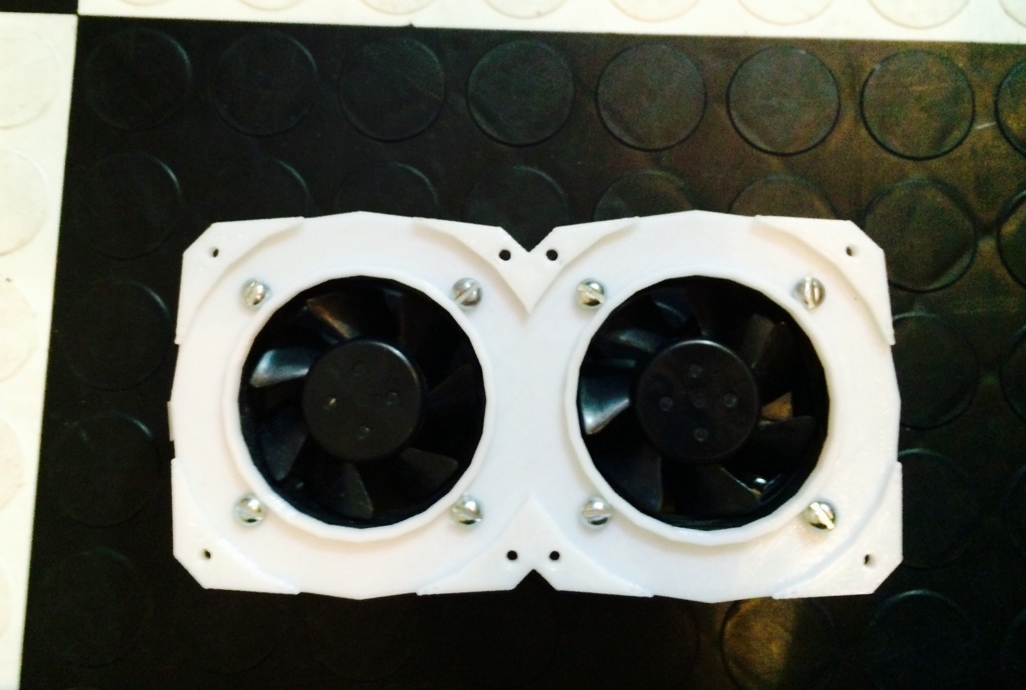
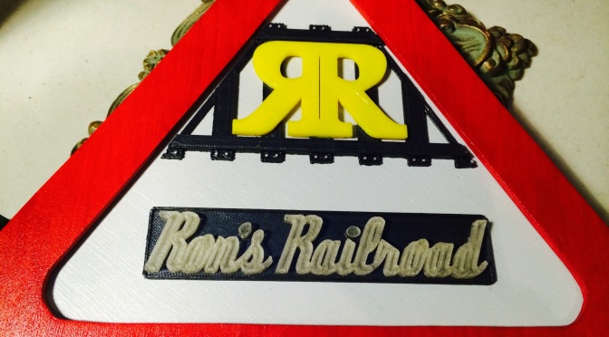
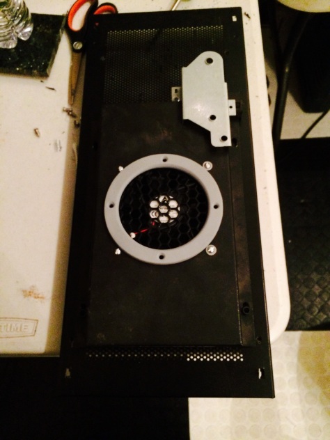
The first design and print we did was for a dual 60mm fan that is case and rad mountable. It came out awesome but we still need to sand and paint it so it can be mounted in our new setup. We will be running two of these – side by side in our new case.

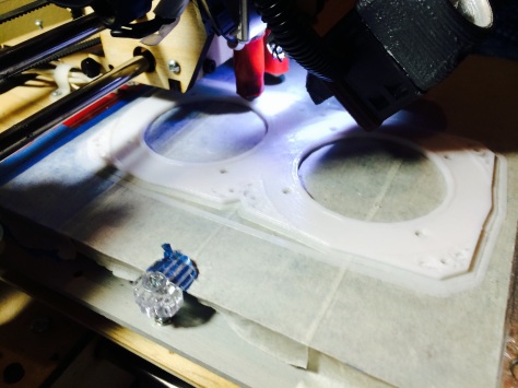
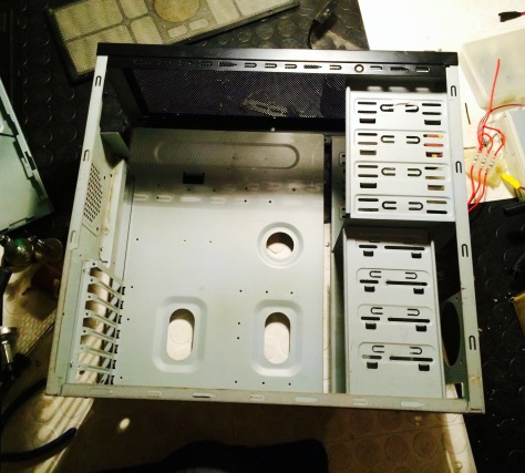
The next parts we decided to build were Cable supports for the motherboard tray. We started by cutting holes in the motherboard tray to feed wiring through the back. This will allow us to hide the wiring. The reason for this is twofold one it increases cooling and two it gives the case and overall clean look.
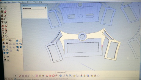
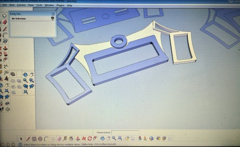
After we cut out our holes we went on Sketchup to design our inserts that would click in our cutouts. We designed several different shapes of cutouts depending on which cables would be routed through that hole. Here’s what the prints looked like after they are mounted:
Official Build Log – Reaper N1
Planned Mods:
• Custom top cover with futuristic/modern styling.
• Custom sleeved wiring with an extensive cable management setup.
• Completely redesigned side panels with added acrylic set on standoffs.
• Custom built, hinged doors and top cover.
• Slide open top with fans and hard drive mounts moved to top.
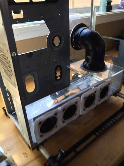
• Painted PSU was moved from top left to bottom right. 2-3″ bent tubing to exhaust all PSU heated air out the side.
• Removed all hard drive cages from donor case. Custom cut down DVD burner mount.
• New panel cutouts in the MB tray with 3D printed pass throughs. (Might build a custom slide out mobo tray)
• Sliding rail system for optical drives and spare HD space.
• Scratch built fan controller using an Arduino Uno or Mega.
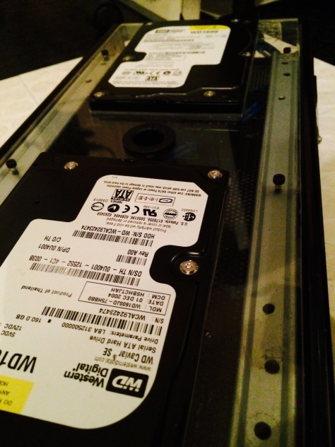
• Top acrlyic mounted dual 250 gig Western Digital SATA drives. (Scratch built cooling)
• Negative Pressure cooling system with filters and sound dampening mount. ( Complete custom designed airflow and cooling system that uses only air management)
• Extensive cable management design with parts designed specifically for this build. ( 3D printed parts FDM out of Nylon or Carbon Fiber reinforced filament.
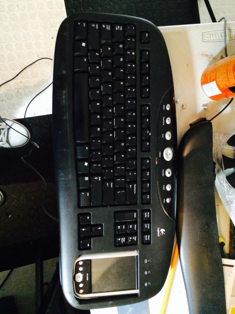
• Modded Logic Sys keyboard with built in touch screen. (Also has wifi, card reader and windows mobile 6.0 OS)
• Scratch built acrylic hard drive mounts. ( 2x Western Digital SATA drives 250 GB )
• Extensive air cooling system and fully vented outer case shell.
• 4x 70mm rad mountable fan mounts ( Custom designed dual fan mounts)
• Full re paint of case and inner shell ( As of now colors will be: white, grey, black and orange. As well as a few carbon fiber parts)
Main Comp Parts Being Used:
• Gigabyte Motherboard with PCI Express. Accepts two types of ram on the same board. Custom Built cooling added with heat pipes, tough cover custom designed, ram cooling system and custom wired reset/power switches.)
• Digital sound card with multi-channel support.
• 2 x 250 GIG Western Digital hard drives and at least two other WD drives. (possible RAId or custom mirror config)
• PCI-Express Video Card (Scratch built cooling)
Intro:
After looking through a bunch of old stuff that I had laying around I decided that it be a good idea to do a full case build. I started by hacking up this old case I had laying around that was originally supposed to be modeled after Mac’s old G4. I wanted to build something that was original something that I’ve never seen before. I went to my local army surplus store, not to get old ammo crates are other things I’ve seen done before. I also didn’t want to back myself into a corner by deciding a specific theme. I’m the kind of person that if I’m gonna do something, I’m gonna do it right and the best I know how the first time. I have a background in 3–D printer design as well as subtractive manufacturing. However I won’t be using a CNC machine for this build I’ve decided to do everything with a more hands-on approach.
I’m also doing this on a budget and I mean a tight budget. There will be a few parts I plan to 3–D print and design myself. There are a few things I want to do accomplish during this build — The first thing I wanted to accomplish was to show everyone that a case can be built cheaply. I see so many cases that you can just tell money was thrown at it and I didn’t want this to be one of them. I don’t have the best parts in the world but hey, isn’t this about what can be done to the design of the case. Molding a combination of cutting edge design with functionality.
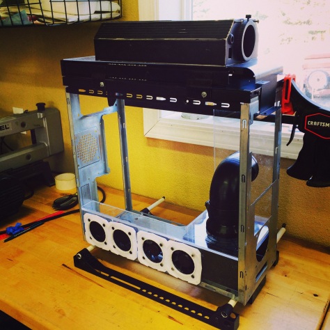
It begins:
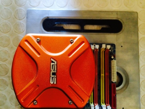
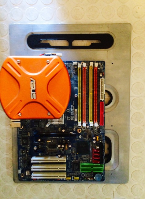
The first thing I did was to strip down the case and take every single piece apart, so I can see what I was working with. To start off, the plan is to make everything nice and neat. That means tucking cables through the new cut outs I will make. I cut out several cable pass throughs on the MB tray. I wanted some to come out right next to the edge of the motherboard and others to come out behind it. I also wanted another cut out to make it easy to remove and add on the CPU Cooler. I will be using a new Asus CPU cooler with 6 heat pipes.
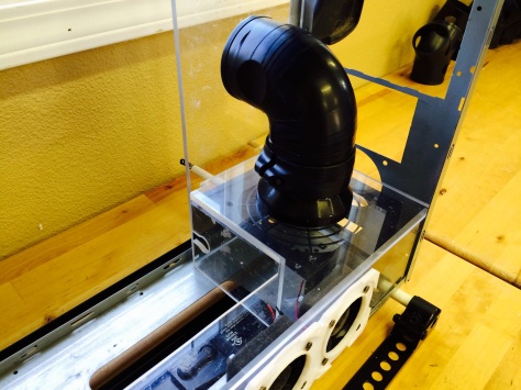
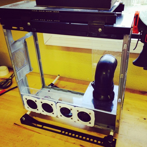
Another idea I’ve been toying around with is the use of this heavy duty hamster fan. I’ve yet to see one used on a case ever. I found one for a reasonable price and ordered it. The trick is it runs off AC voltage regulated through a small transformer. Typically I don’t mess with A/C but, for this case I’ll make and exception. I will have to map out the fan intake and exhaust ports once I get the overall layout finished. That way I can decide whether the hamster fan will pull air in or push air out. Given the placement more than likely I will have it suck hot air out as hot air rises.
Another perk that I splurged on with the little budget I had was a touch sensitive button. More than likely it will be used to turn on and off the computer. I also have a great idea for how to power all the stuff that will be mounted on the side panels without running wiring all over, more on that later. Another feature I’m interested in which is nothing new, is opening the side and top panels in a new fashion. I have yet to decide how they will open but more than likely I will use some sort of hinge setup.
Current Progress
Still mocking up different ideas but here’s what we have finished so far:
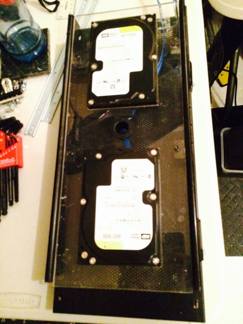
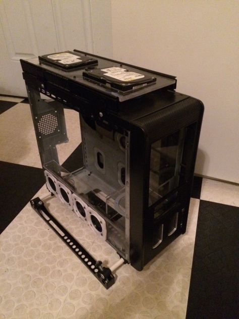
Last night and this morning we were able to cut the acrylic for the hard drive mounts. They will be mounted on a track system, which will open up the top of the case. Both of these hard drives will be fan cooled. It took quite a bit of time as we cut the acrylic out with a scroll saw and then filed it for a perfect fit. Hopefully today I can get all the finish work and polishing done on all the acrylic panels.
I still haven’t decided 100% on what I’m going to use for the standoffs on both side panels. More than likely I will use some aluminum ones I have. I also need to cut the cooling hole for the 120 mm top PSU fan which will be ran through a duct to the outside of the back side panel.
I was able to mount the two top mounted hard drives in their acrylic supports. I still need to design the bezals for both of them as well as do some cutouts on the top of the case.
I went back through the motherboard backplate and decided to take a little more off. I did this in order to offer up more space to take off the CPU cooler. More than likely I will design a custom cover for the cutout.
I have made the first few cuts on the custom matching keyboard. It will have a touch screen PDA built in where the number section used to be. So far I’ve stripped out the insides, cut out a spot for the PDA and remove some of the electronic pieces that will no longer be needed.
.
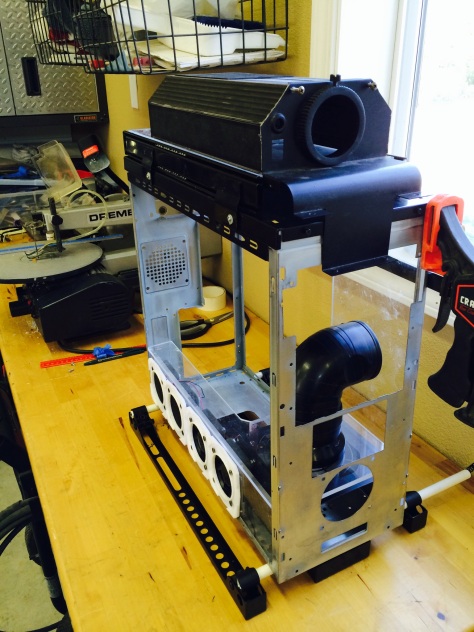
Today I’m going to focus on finishing up the mounts for the bottom of the case. The The feet will consist of three rails, two outside rails and one thicker inside rail. I will be building a suspension system and mounting that the case with custom 3-D printed mounts that follow the cases overall styling. I was able to get the four bar mounts printed today and those will hold the feet to the case. I also need to print out a few pieces that I’m designing for the end caps.

The bezels for the two top mounted hard drives still need to be designed. More than likely I will also design the mounts for the acrylic panels for the inside of the case at the same time. Once I have the main design features finished and mocked up I can start on adding all of the smaller touches. I am a very detail oriented designer and excel when it comes to these parts.
Mock ups have been started for the ribcage cooling setup. It will have two 80mm fans which will cool the two top mounted hard drives. I still need to figure out where I’m going to put my external 500 gig Western Digital hard drive. More than likely I will build a custom matched stand unless, I can incorporate it into the case somehow.

I was also able to get all of the aluminum stand-offs I needed for the acrylic panels that will be mounted on the side panels. Next week I will start sketching out the design of the other side panel. I will have to incorporate the PSU exhaust into this panel.
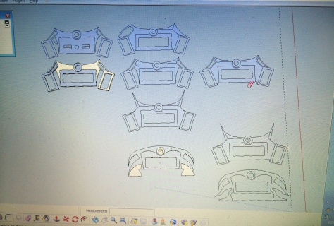
The rod in the above picture is for the custom ribcage cooling system I’m building. It will have a bunch of thin 3d printed panels that taper down on each plate. It will have two fans mounted horizontally to cool the top two motors. Here are some of the rough designs in Sketchup. As you can see I made about 10-15 iterations before finding one I liked.